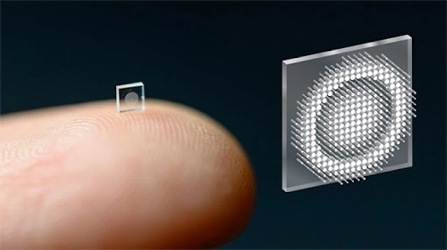
Over the last several decades, the reduction of intensity sensors has made cameras widespread in a variety of applications, including medical imaging, mobile smartphones, security, robotics, and autonomous driving. Smaller order-of-magnitude imagers, on the other hand, might open up a slew of new possibilities in nanorobotics, in vivo imaging, AR/VR, and health monitoring.
Additionally, the rich modal characteristics of meta-optical diffusers can support multifunctional capabilities beyond what traditional DOEs can do (eg, polarization, frequency, and angular multiplexing). Meta-optics can be fabricated using widely available integrated circuit foundry techniques, such as deep ultraviolet lithography (DUV), without multiple steps of etching, diamond turning, or grayscale lithography, such as those used in polymer-based DOEs or in binary optics. Because of these advantages, researchers have exploited the potential of meta-optics to construct flat optics for imaging5,6,7, polarization contro8, and holography9.
Existing metasurfaces imaging methods, however, suffer from an order of magnitude greater reconstruction error than that obtainable with refractive composite lenses due to severe wavelength-dependent aberrations that result. discontinuities in their allocated phase 2,5,10,11,12,13,14,15,16.Dispersion engineering aims to mitigate this by taking advantage of group delay and group delay dispersion to focus broadband light 15,16,17,18,19,20,21, however, this technique is primarily limited to aperture designs of ~ 10s of micron22. Therefore, existing approaches have not been able to increase the achievable aperture size without significantly reducing the numerical aperture or the range of wavelengths supported.
Other solutions tried are sufficient only for discrete wavelengths or narrowband illumination11,12,13,14,23 Metasurfaces also exhibit strong geometric aberrations which have limited their utility for wide-field imaging. vision (FOV) Approaches that support a large FOV typically rely on small entry apertures that limit light collection24 or use multiple metasurfaces11, greatly increasing the complexity of fabrication.
Outcome
Model of a differentiable metasurface proxy
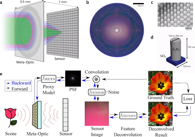
The proposed differentiable metasurface imaging model (Fig.1e) consists of three sequential steps using differentiable tensor operations: metasurface phase determination, PSF simulation and convolution, and sensor noise. In our model, the polynomial coefficients which determine the phase of the metasurface are optimizable variables, while the experimentally calibrated parameters characterize the reading of the sensor and the distance from the metasurface of the sensor are fixed. Our ultra-thin meta-optics learned as shown in (a) has a thickness and diameter of 500 m, allowing the design of a miniature camera. The optics produced are illustrated in (b). A zoom is shown in (c) and the dimensions of the nano post are shown in (d). Our end-to-end imaging pipeline illustrated in e is composed of the proposed efficient metasurface imaging model and feature-based deconvolution algorithm. From the optimizable phase profile, our differentiable model produces spatially varying PSFs, which are then patch convolved with the image input to form the sensor metric. The sensor reading is then deconvoluted using our algorithm to produce the final image. The above illustrations “MetaOptic” and “Sensor” in (e) were created by the authors using Adobe Illustrator.
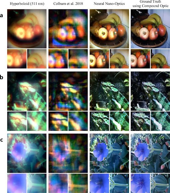
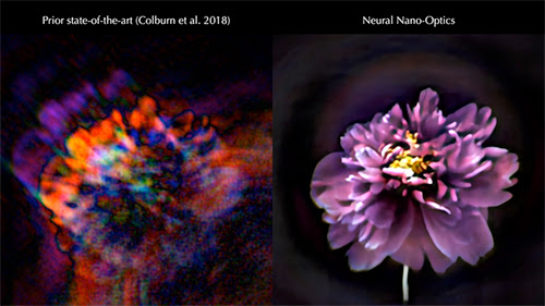
Compared to existing state-of-the-art designs, the proposed neural nano-optics produce high-quality aberration-corrected FOV reconstructions. Examples of reconstructions are shown for a still life with fruits in (a), a green lizard in (b) and a blue flower in (c). We compare our reconstructions with ground truth acquisitions using high-quality six-element composite refractive optics and demonstrate accurate reconstructions even though our meta-optics volume is 550,000 times smaller than that of composite optics.
Description of meta-optics.
The proposed learned meta-optics is fabricated using electron-beam lithography and dry etching and the corresponding measured PSF, simulated PSF and simulated MTF are presented. Before acquiring the images, we first measure the PSFs of the manufactured meta-optics to take into account the deviations from the simulation. However, the correspondence between simulated and measured PSFs validates the accuracy of our metasurface proxy model. The proposed learned design maintains a consistent PSF shape across the visible spectrum and for all viewing angles through the FOV, facilitating downstream image reconstruction. The traditional meta-optic PSFs and the cubic design proposed by Colburn et al.10 both exhibit severe chromatic aberrations. The red (606nm) and blue (462nm) PSFs of traditional meta-optics are blurred and change significantly across the FOV. PSFs for the cubic design feature long tails that leave post-deconvolution artefacts.
Optimize
We used TensorFlow 2 to design and evaluate our neuronal nano-optics. See Supplementary Note 6 for more details on the learning procedure, hyperparameters, and loss functions. We used the INRIA Holiday data set for training36.
Fabrication of samples
Starting with a double-sided polished fused silica wafer, we deposit 705nm of silicon nitride via plasma-assisted chemical vapour deposition to form our device layer. JEOL JBX6300FS electron beam lithography system at 100 kV and 8 nA. After stripping the gold, we develop amyl acetate followed by immersion in isopropyl alcohol. To define the etching mask, we evaporate 50 nm of aluminium and detach it by sonication in methylene chloride, acetone and isopropyl alcohol. We then etch the silicon nitride layer using CHF3 and SF6 chemistry with an inductively coupled plasma engraver. to define a rigid opening to block the flare.
Setup for the experiment
After manufacturing the meta-optics, we take into account the manufacturing error by performing a PSF calibration step. This is achieved by using an optical relay system to visualize a pinhole illuminated by fibre-coupled LEDs. Next, we conduct imaging experiments by replacing the pinhole with an OLED monitor. The OLED monitor is used to display the images that will be captured by our nano-optical imager. For more details, see Supplementary Note 7.
Data accessibility
The raw data from the capture is accessible. https://doi.org/10.5281/zenodo.5637678.

